Face it: Your original muscle car’s headlights and taillights are old. Maybe they’re still as good as they ever were, but the world has changed around them. Drivers today are more distracted than ever, and even the most bland, blob-shaped commuter junk has better lighting than your prized stock GTO, Charger or Mustang. Do you really want to gamble that you’re going to be seen when you brave modern traffic in your classic machine?
With a little work, you can inject modern lighting technology into your classic car without changing its OE looks or hacking up its original wiring.
That’s what we did with ACC Contributor Jay Harden’s ’69 Chevelle — installing a set of headlight relays and a set of Digi-Tails LED taillights at World of Speed in Wilsonville, OR. Don’t let the wiring intimidate you — these are easy projects. Here’s how we did it:
Headlight Relays: From the factory, this Chevelle’s headlight power had to run from the battery into the interior, through the headlight switch and high-beam foot switch, and back out to the lights. It’s not the most direct connection, and there’s some substantial voltage drop in all that old wire and all those old connections.
We’re still going to use the factory setup, but only to trigger a set of brand-new relays, which takes next to no juice. All the load on the circuit will be gone, yet the factory switch, dimmer, high-beam indicator and warning buzzer will all still work.
Summit Racing Parts List
- Pico 40-amp mini relay, P/N PCO-5591PT, $6.97/each (2 required)
- Vintage Air 30A Circuit Breaker, P/N VTA-23160-VUW, $8.97
- Ron Francis Wiring Sealed Beam Connectors, set of 8, p/n RFW-AM8 $12.69/each (2 required)
- Standard Motor Headlight Plugs, 2-wire (high beam), p/n SMP-S529, $5.97/each (2 required)
- Standard Motor Headlight Plugs, 3-wire (low & high beam), p/n SMP-S526, $4.97/each (2 required)
- Pico wire, 16-gauge brown, p/n PCO-81166PT, $4.97
- Pico wire, 16-gauge green, p/n PCO-81164PT, $4.97
- Pico wire, 16-gauge black, p/n PCO-81163PT, $4.97
- Pico wire, 14-gauge green, p/n PCO-81144PT, $5.97
- Wire, 14-gauge brown, p/n RNB-85717, $6.97
- Wire, 12-gauge red, p/n SUM-872100R, $21.97
- Performance Tool 285-piece electrical repair kit, p/n WMR-W5207, $24,97
- 171-piece heat-shrink tube kit, p/n TTN-45238, $9.97
- Convoluted tubing kit, various sizes, p/n TAY-38000, $16.97
- Cordless butane soldering iron kit, p/n ECG-J-700KT, $58.95
Digi-Tails Parts List
- 1969 Chevelle Sequential LED Tail Light Kit, P/N 1100469, $199
- Digi-Tails No-Load electronic flasher for LED, two-prong, $19
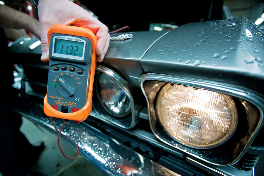
How dim are your lights? Most GM muscle cars will show about 11.5 volts through the original headlight circuit wiring with the engine running. Jay’s was 11.32. Considering the alternator puts out over 13 volts at idle, we can do a lot better here — and we’re going to do it using modern relays. 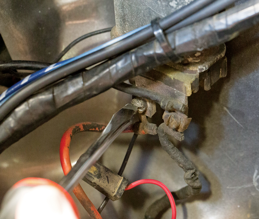
Headlight power will instead come from the original horn-relay bus bar — fed power directly from the alternator. You could also run a wire to the positive terminal of the battery, but using the horn relay requires a lot less wire length. Once you’ve located what will serve as your main power supply for the headlights, disconnect the battery. 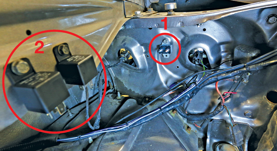
Next up: finding a suitable mounting location for a 30A circuit breaker and the two headlight relays. The breaker needs to be mounted between the relays and the main power supply, used to cut power in case of a short. Here we found a spot on the core support for the breaker, not far from the horn relay (1). The two relays bolted to two existing holes in the driver’s fender (2). We also drilled a new hole to serve as a ground. 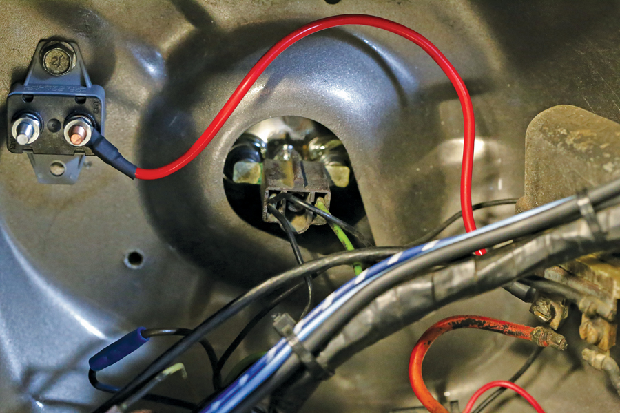
Feeding power to the breaker is a simple as fabbing up a short section of 12-gauge wire. We crimped and soldered the ends using a butane soldering iron (fantastic and portable) and used shrink-tube to keep out moisture. One end connects to the positive screw on the horn relay, the other to the new circuit breaker. 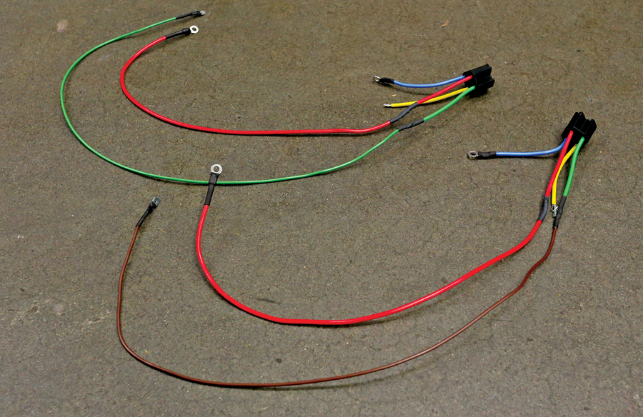
Each relay came with its own pigtail and plug. We just needed to extend the wires out for our use. Here, the red wires link to the breaker to feed main power to the relays. Blue is main ground for both, while green and brown are trigger wires, used to match the factory harness colors. Finally, yellow runs to the headlights. 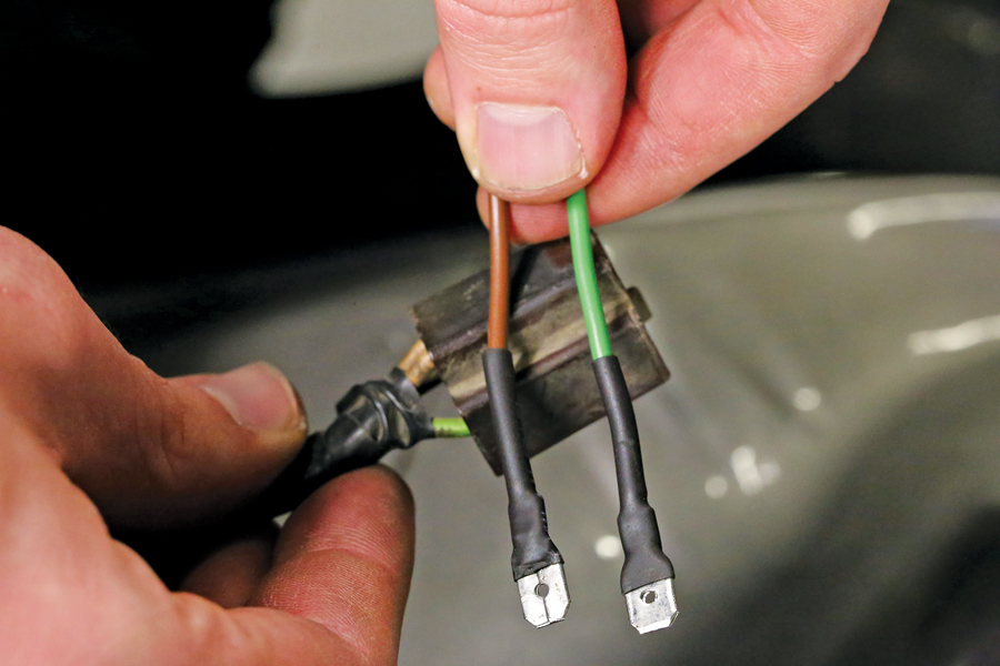
We used spade connectors on our new 16-gauge relay trigger wires. These simply plug into one of the original low-beam headlight plugs to trigger our new relays when the headlight switch is on. You could also cut the original harness and hard-wire these to the factory high- and low-beam circuits, but we wanted to maintain the original harness’ integrity. 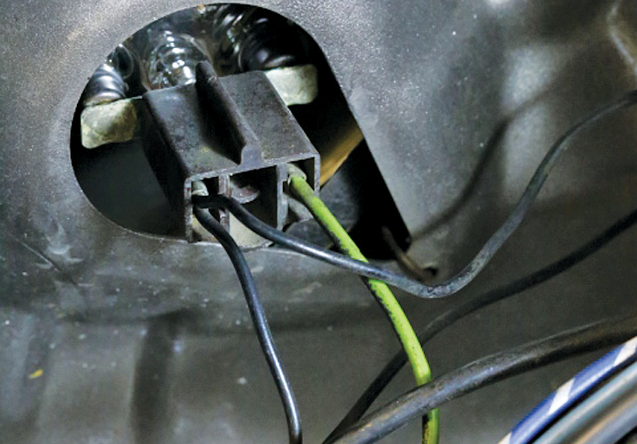
The factory headlight wiring used small 16-gauge wires. We’re beefing that up for this project with brand-new 14-gauge brown and green wires to run from the relays to the headlights. The goal is limiting voltage drop as much as possible — which will translate to brighter lights. 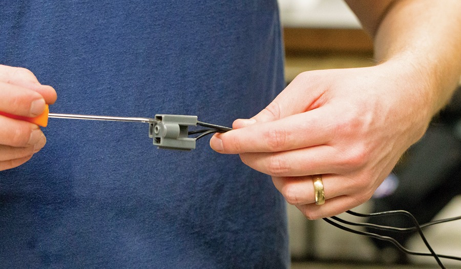
We also sourced new plugs for all four headlights, but they also came with dinky wires that were too small for our purposes. Ron Francis Wiring makes the proper plug ends to accept heavier gauge wire, so we used them. Taking out the metal connectors from the plastic plugs is easy with a really small screwdriver. Just bend back the spring tab and pull on the wire. 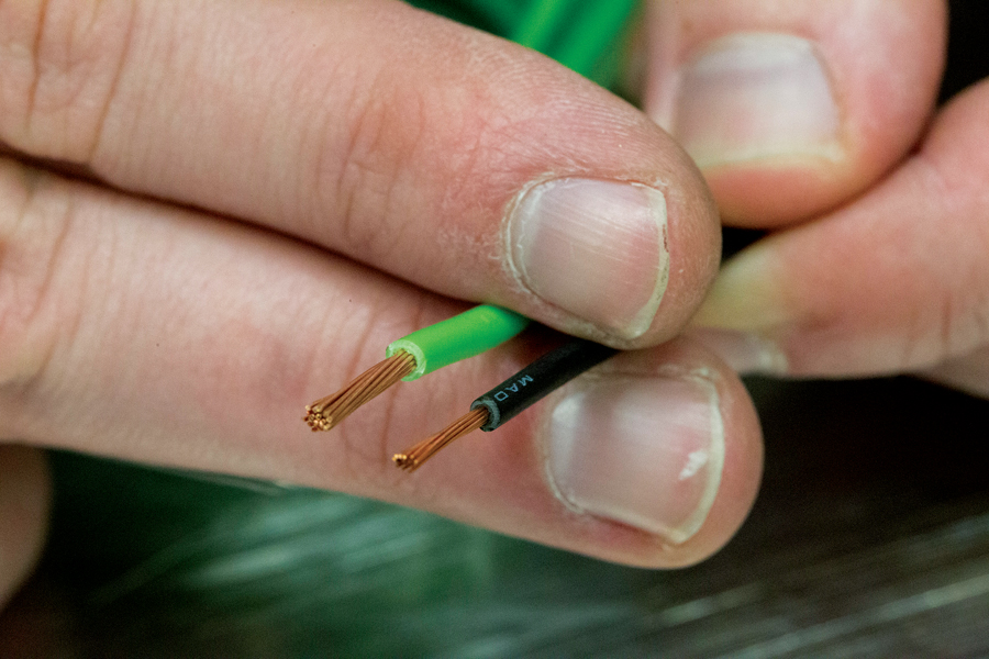
Here’s a good comparison of the factory-size wire with our new 14-gauge headlight feeds. Bigger is better here. 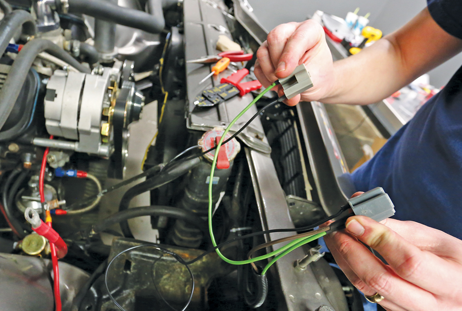
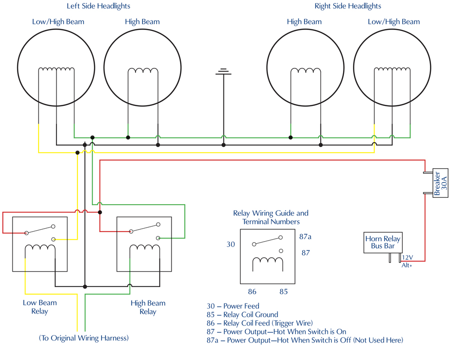
Using all new 14-gauge wire and the Ron Francis Wiring terminals, we ran power from the high-beam and low-beam relays out to the headlights. High beam (green) runs in series to all four headlights, low beam (brown) only goes to the outermost lights. We soldered all connections and used shrink tube to keep it all clean. 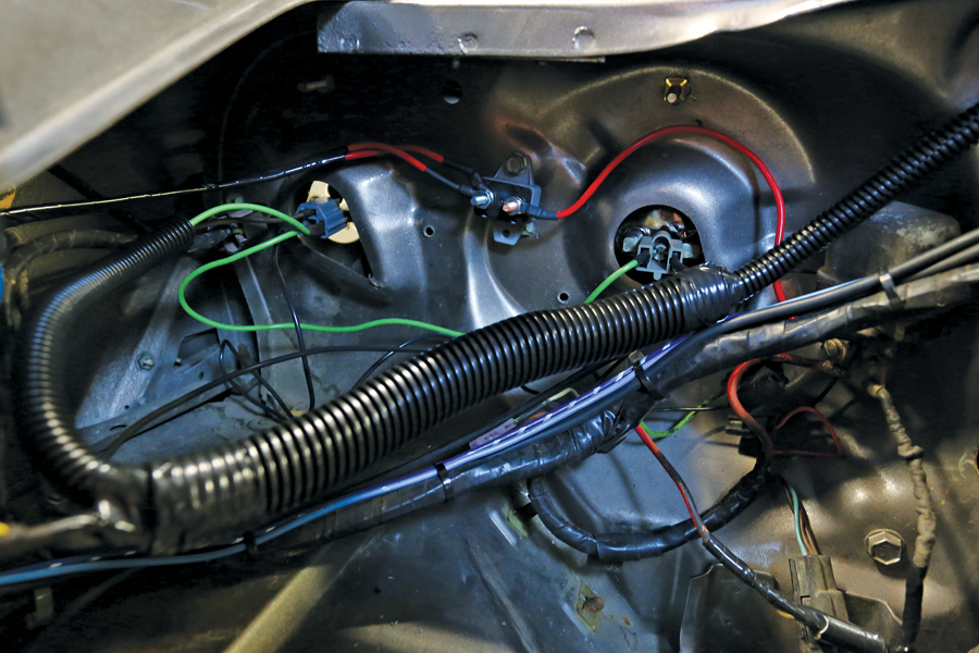
We simply unplugged the original headlight plugs and wire-tied them to the harness, up out of the way where they can’t touch anything. You could remove the factory plugs, shrink-tube the wires, and wrap-tape them up in the original harness, but with the plugs intact, you can revert back to the factory setup on the side of the road if needed. 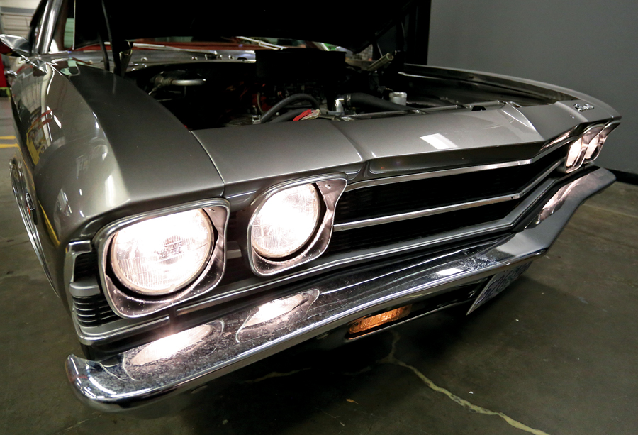
Once everything is plugged in, wrapped up, tucked away, and grounded as required, hook up the battery and hit the lights. Now, with the engine running, we’re seeing a much brighter 13V+ at the headlights, and the factory switch no longer gets hot. Problem solved! Best of all, none of the changes made here are permanent.
Headlight Wiring Diagram
Now We’re Ready to Tackle the Taillights …
Switching over is simple, but there are some important steps to follow:
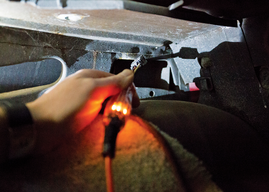
Identify a constant-power source in trunk or rear compartment with a test light. We found an orange wire that fed power to the dome light, which is perfect. After you’ve done that, disconnect the battery. 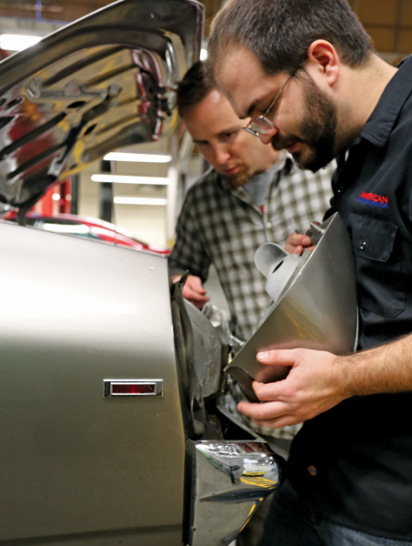
Remove taillights. We had to drop Jay’s bumper here, so take care to mark your bolts for painless reinstallation if that’s your case as well. 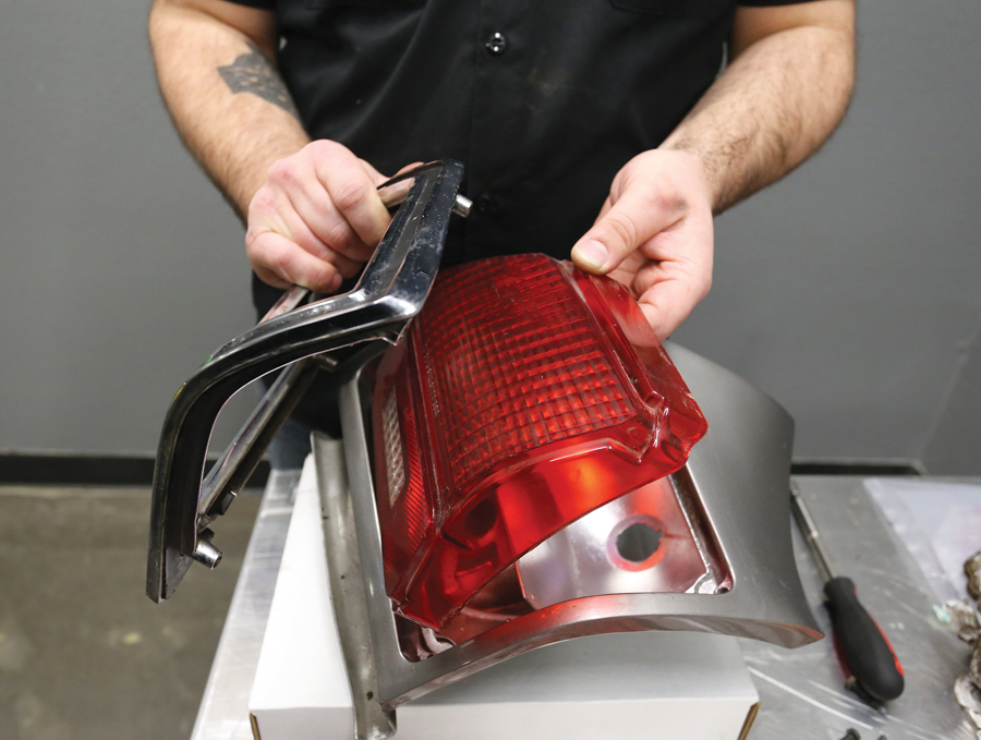
Disassemble taillights. Go easy on the 45-year-old-plus plastic lenses. Now is a great time to inspect for disintegrated gaskets and other maladies. 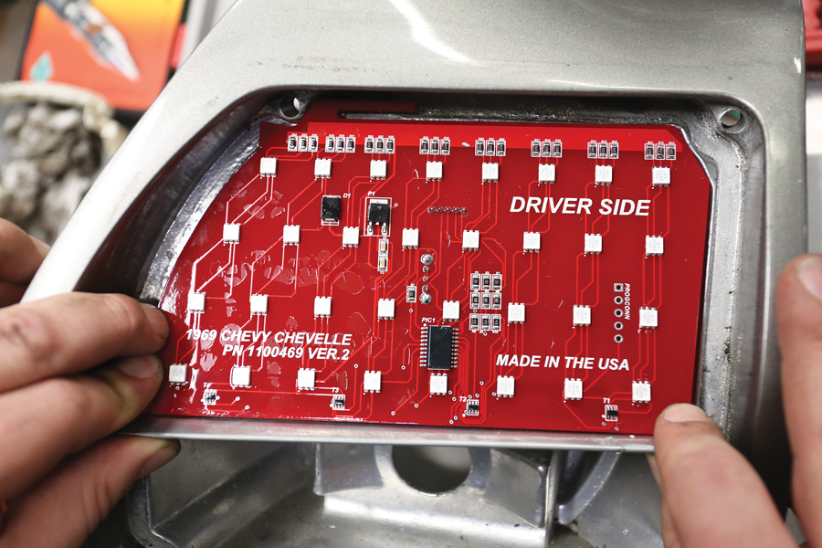
Test-fit the new Digi-Tails LED panels. Also ensure both panel switches are set to the same position, i.e. Standard or Sequential. Standard functions the same as stock (only much brighter), while Sequential illuminates rows of diodes from the center of the car out. If you don’t like the setting you’ve picked, changing it up is as simple as flipping each switch. 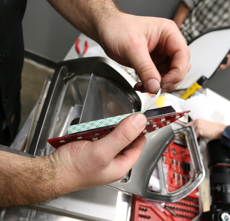
Apply adhesive, or, in our case, peel the paper from the tape and install each LED panel. Press firmly and allow adhesive to set for a few minutes. 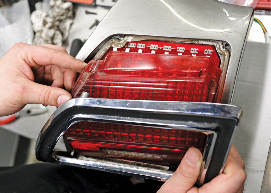
Assemble housing. Here’s where you would replace those 47-year-old gaskets. 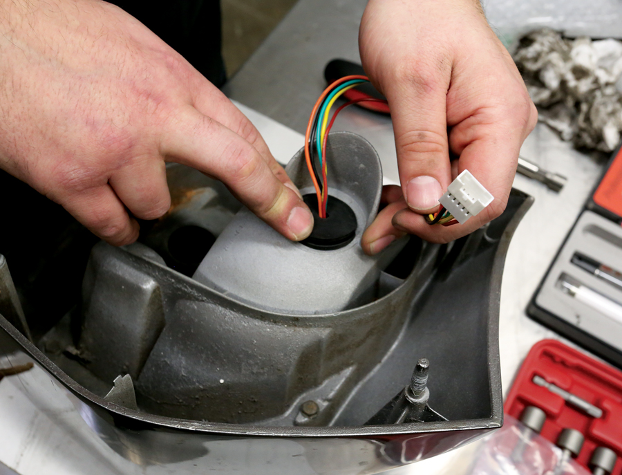
Plug in extension wires, supplied with the kit, and install grommets. A flat-blade screwdriver is handy at this point. 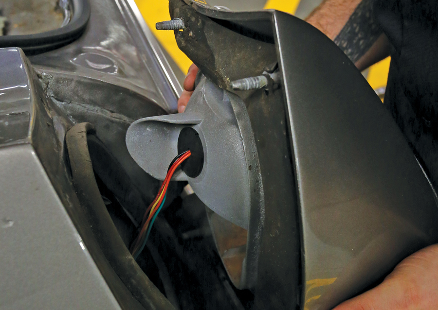
Reinstall taillight housings, taking care to avoid scratching the paint. Wait on repositioning the bumper until you’re sure your wiring is done and functioning correctly. 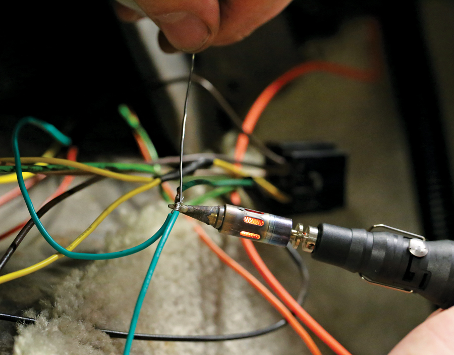
Access taillight wiring and splice the new LED panel wires into your original wiring as instructed. Both panels need to be hooked up to the same wires, so it’ll help to lay everything out before splicing. For a secure connection during one of Jay’s burnouts, we soldered and then applied heat-shrink tubing to each of the connections 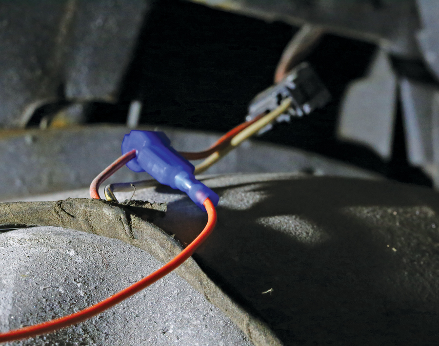
Splice orange constant-power wire into constant-power source in trunk with supplied T-tap. We’re almost there… 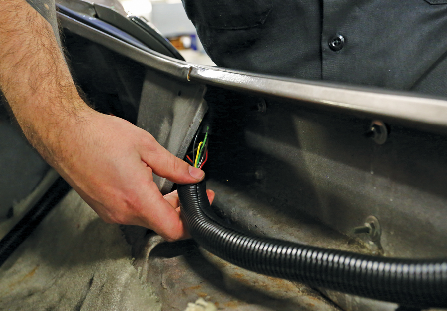
Secure all spliced wiring. This can be done with wire ties, plastic loom, electrical tape, etc. 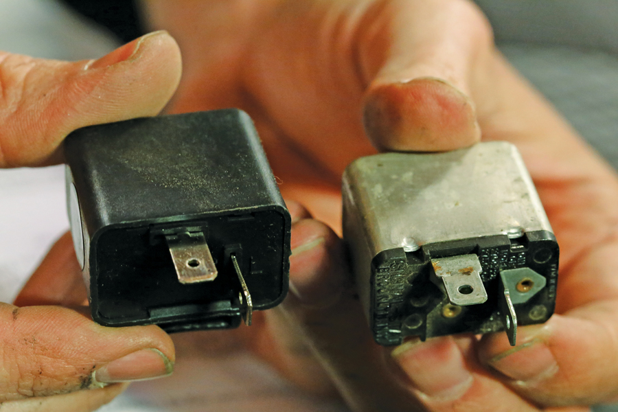
Digi-Tails require replacing the turn-signal flasher with an electronic no-load flasher. A stock or heavy-duty bi-metal flasher needs more resistance load to function properly than an LED panel creates. This is certainly true for cars equipped with front and rear LED turn signals. Reconnect the battery and test to verify everything works. 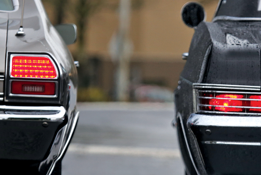
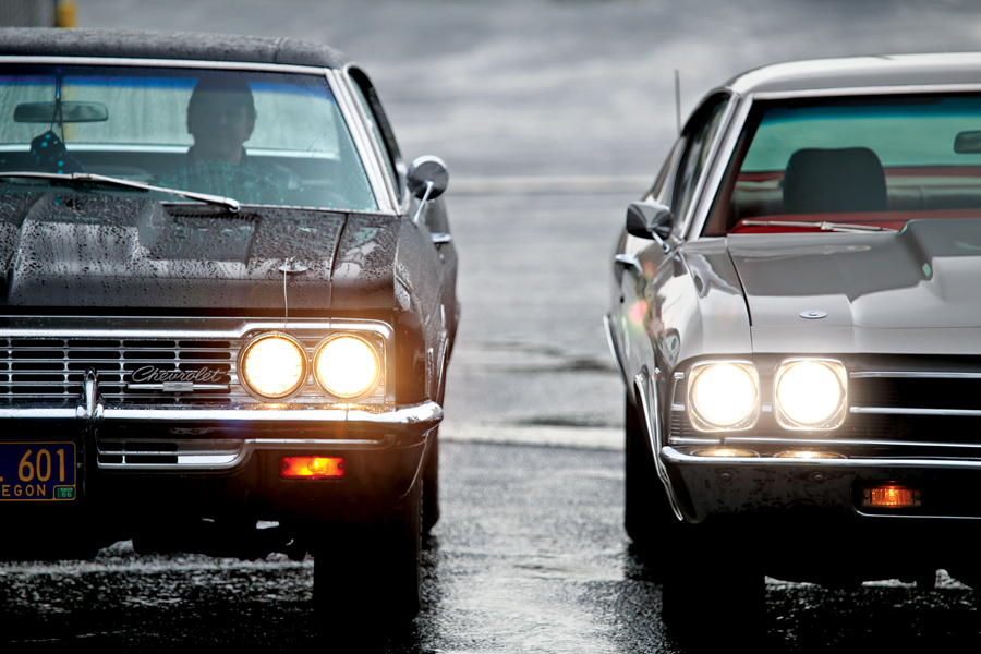
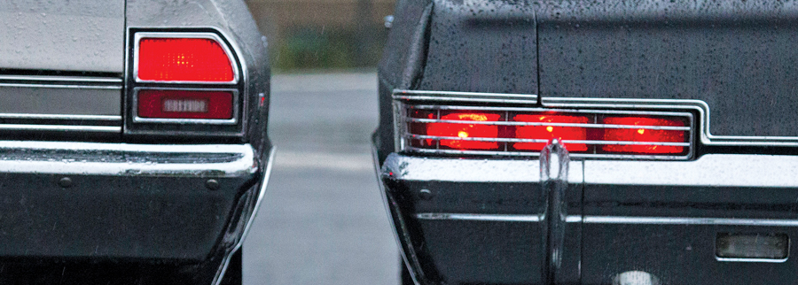
Next to Editor Pickering’s Caprice and its stock taillights, Jay’s Chevelle now has much brighter units — and they should never need attention as long as he owns the car.