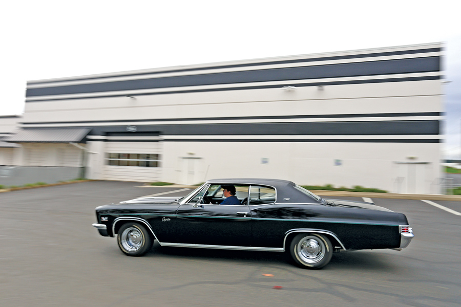
First impressions are a big deal in the car world, especially at auction. A car might only have a minute or so in the spotlight, and having it look just right for that minute can mean a difference of thousands of dollars on your bottom line.

Nothing can make or break a car’s aesthetic more than its stance. Is the nose too high up in the clouds due to reproduction big-block springs? Maybe it’s too far down in the weeds on dropped spindles and cut springs. In the past these sorts of adjustments were an all-or-nothing deal — spend hundreds on the parts, hope for the best, and live with the results. Not anymore.

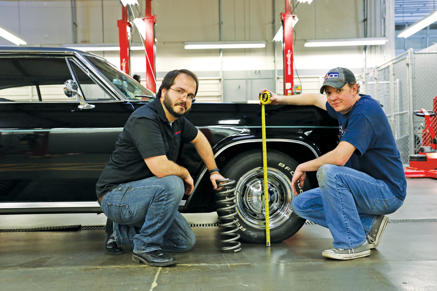
QA1 Precision Products’ Pro Coil coil-over suspension system is an innovative design that allows complete control over your car’s ride height without making irreversible modifications to the underlying frame or control arms.

It’s a shock and a spring in one, designed to fit where the factory spring sits and engineered to give you adjustability you never could have dreamed of with factory parts. You have a choice of spring rates to get you started, as well as standard, single adjustable, or double adjustable shock (compression and rebound) to dial in the ride quality you want.

We got a set and headed down to World of Speed in Wilsonville, OR, to show you just how simple getting that right height can be.

  1. Call QA1 (1.800.721.7761) to discuss your car and its spring-rate needs. Once that’s nailed down and your parts are in hand, measure your car’s ride height from the ground to the center of the wheelwell. In this case, our full-size ’66 Chevy is at 28 inches. Then jack up and support the car so its suspension hangs at full droop and remove the front wheel.
    Call QA1 (1.800.721.7761) to discuss your car and its spring-rate needs. Once that’s nailed down and your parts are in hand, measure your car’s ride height from the ground to the center of the wheelwell. In this case, our full-size ’66 Chevy is at 28 inches. Then jack up and support the car so its suspension hangs at full droop and remove the front wheel.
  2. Loosen and remove the upper shock-mount nut, the steel washer and the upper rubber isolator bushing. Then remove the lower shock-mount bolts from the lower control arm.
    Loosen and remove the upper shock-mount nut, the steel washer and the upper rubber isolator bushing. Then remove the lower shock-mount bolts from the lower control arm.
  3. Remove the shock, being careful not to lose any of its mounting hardware. Thread the washers, bushings and retainer nut onto the shock — just in case you ever want to go back to stock.
    Remove the shock, being careful not to lose any of its mounting hardware. Thread the washers, bushings and retainer nut onto the shock — just in case you ever want to go back to stock.
  4. Coil-over: Step 4
    Remove the shock, being careful not to lose any of its mounting hardware. Thread the washers, bushings and retainer nut onto the shock — just in case you ever want to go back to stock.
  5. Next up, disconnect the sway bar end link, and thread all the hardware back onto the mounting bolt so you don’t mix up the order of bushings, washers and sleeves.
    Next up, disconnect the sway bar end link, and thread all the hardware back onto the mounting bolt so you don’t mix up the order of bushings, washers and sleeves.
  6. The most complicated part of this process is removing the factory spring. We rented a spring compressor to keep the spring’s power under control. Run the compressor through the upper shock-mount hole in the frame, set its arms to hold the spring, and tighten it up slightly.
    The most complicated part of this process is removing the factory spring. We rented a spring compressor to keep the spring’s power under control. Run the compressor through the upper shock-mount hole in the frame, set its arms to hold the spring, and tighten it up slightly.
  7. Remove the cotter key from the lower ball-joint castle nut and loosen it a few turns, but don’t remove it yet.
    Remove the cotter key from the lower ball-joint castle nut and loosen it a few turns, but don’t remove it yet.
  8. Next, separate the lower ball joint from the spindle. It’s a tapered press fit, so don’t expect this to go easily. We started with the two-hammer method — hit one side of the spindle while holding a hammer on the other to rattle the taper loose. Note the position of the castle nut — when the taper lets go, that nut will keep the coil spring from escaping.
    Next, separate the lower ball joint from the spindle. It’s a tapered press fit, so don’t expect this to go easily. We started with the two-hammer method — hit one side of the spindle while holding a hammer on the other to rattle the taper loose. Note the position of the castle nut — when the taper lets go, that nut will keep the coil spring from escaping.
  9. In our case, 30 minutes of hammering wasn’t enough to get the job done, so we employed a pickle fork on an air chisel, which took five seconds. Note the floor jack, placed to help control the spring.
    In our case, 30 minutes of hammering wasn’t enough to get the job done, so we employed a pickle fork on an air chisel, which took five seconds. Note the floor jack, placed to help control the spring.
  10. With the ball-joint taper loose, set the jack to take some weight off the lower control arm, remove the castle nut, and then jack up until the ball joint clears the lower spindle. Pull the spindle aside and slowly let the jack down a few inches.
    With the ball-joint taper loose, set the jack to take some weight off the lower control arm, remove the castle nut, and then jack up until the ball joint clears the lower spindle. Pull the spindle aside and slowly let the jack down a few inches.
  11. Lower the jack slowly until the control arm stops moving (due to the spring compressor holding the spring), and then loosen the spring compressor until the spring is free. We used the jack here as a backup to control the spring on its way out.
    Lower the jack slowly until the control arm stops moving (due to the spring compressor holding the spring), and then loosen the spring compressor until the spring is free. We used the jack here as a backup to control the spring on its way out.
  12. Next, remove the two spot-welded nuts used to hold the lower end of the shock to the lower control arm. A quick blast from an air chisel is the simplest way — but be sure to find and keep them.
    Next, remove the two spot-welded nuts used to hold the lower end of the shock to the lower control arm. A quick blast from an air chisel is the simplest way — but be sure to find and keep them.
  13. We also used a burr to clean up the Pro Coil mounting area on the lower control arm. The factory 5/16-inch holes need to be opened up to 3/8-inch to accommodate new grade-8 mounting bolts.
    We also used a burr to clean up the Pro Coil mounting area on the lower control arm. The factory 5/16-inch holes need to be opened up to 3/8-inch to accommodate new grade-8 mounting bolts.
  14. Now we can assemble the QA1 Pro Coil unit. First, coat the shock-body threads with anti-seize, and then thread the lower lock nut and the adjuster nut onto the shock body. We also used QA1’s optional thrust-bearing kit, which includes a roller bearing and two steel washers, seated between the spring and the adjuster nut. This makes ride height adjustments much easier.
    Now we can assemble the QA1 Pro Coil unit. First, coat the shock-body threads with anti-seize, and then thread the lower lock nut and the adjuster nut onto the shock body. We also used QA1’s optional thrust-bearing kit, which includes a roller bearing and two steel washers, seated between the spring and the adjuster nut. This makes ride height adjustments much easier.
  15. Next comes the spring, in this case a 550-pound unit to handle the heft of a heavy Chevy with a big block under the hood. It slides down over the shock and sits, tapered side down, on the adjusting nut. Note the two knobs at the base of the shock — this is QA1’s double adjustable Pro Coil shock, which features independent compression and rebound adjustments. Also note we have the height adjustment set at its lowest possible point.
    Next comes the spring, in this case a 550-pound unit to handle the heft of a heavy Chevy with a big block under the hood. It slides down over the shock and sits, tapered side down, on the adjusting nut. Note the two knobs at the base of the shock — this is QA1’s double adjustable Pro Coil shock, which features independent compression and rebound adjustments. Also note we have the height adjustment set at its lowest possible point.
  16. Pull the shock’s piston rod out to full extension, and slide the upper shock steel washer and rubber isolator onto it. Then thread the entire unit into the car, making sure the extended rod slides through the factory shock mount. Slide the other rubber isolator and steel washer onto the shock’s threads on the upper part of the frame, and install the nut to hold it all in place.
    Pull the shock’s piston rod out to full extension, and slide the upper shock steel washer and rubber isolator onto it. Then thread the entire unit into the car, making sure the extended rod slides through the factory shock mount. Slide the other rubber isolator and steel washer onto the shock’s threads on the upper part of the frame, and install the nut to hold it all in place.
  17. Line up the lower shock mount to factory shock-mount holes in the lower control arm. Note the shock now sits on top of the control arm, compared with the factory under-arm location. Thread the new grade-8 bolts through the lower holes and tighten them down. Compression and rebound setting knobs should point out.
    Line up the lower shock mount to factory shock-mount holes in the lower control arm. Note the shock now sits on top of the control arm, compared with the factory under-arm location. Thread the new grade-8 bolts through the lower holes and tighten them down. Compression and rebound setting knobs should point out.
  18. Impala frames use a clocked upper spring pocket, so the spring must be seated in the proper location. We held the spring up, turned it until it hit its stop inside the frame, and then threaded the ride-height-adjuster nut up to hold the spring’s location in the pocket.
    Impala frames use a clocked upper spring pocket, so the spring must be seated in the proper location. We held the spring up, turned it until it hit its stop inside the frame, and then threaded the ride-height-adjuster nut up to hold the spring’s location in the pocket.
  19. This is a great time to inspect your ball joints and replace if needed — we replaced the boots on ours after tearing them with the pickle fork, but the joints were fine. Now, using the floor jack, jack up on the lower control arm, line up the lower ball joint to the spindle, and then drop the jack back down, seating it.
    This is a great time to inspect your ball joints and replace if needed — we replaced the boots on ours after tearing them with the pickle fork, but the joints were fine. Now, using the floor jack, jack up on the lower control arm, line up the lower ball joint to the spindle, and then drop the jack back down, seating it.
  20. Reinstall the castle nut and torque it. Be sure to install a new cotter pin to retain the nut. Reinstall the strut-rod link to the lower control arm, as well as the sway-bar end links. Also tighten up the upper shock-mount nut — but only enough to expand the rubber bushing out to its washer.
    Reinstall the castle nut and torque it. Be sure to install a new cotter pin to retain the nut. Reinstall the strut-rod link to the lower control arm, as well as the sway-bar end links. Also tighten up the upper shock-mount nut — but only enough to expand the rubber bushing out to its washer.
  21. Coat the shock’s threads in anti-seize again, and using the spanner wrench included in the thrust-bearing kit, adjust the spring seat up. We found that about two inches of threads exposed under the lock nut gave us a factory ride height. Once you have the height adjusted roughly where you want it, run the lock nut up and snug it to the adjuster. Now, starting back on step 1, convert the other side of the car.
    Coat the shock’s threads in anti-seize again, and using the spanner wrench included in the thrust-bearing kit, adjust the spring seat up. We found that about two inches of threads exposed under the lock nut gave us a factory ride height. Once you have the height adjusted roughly where you want it, run the lock nut up and snug it to the adjuster. Now, starting back on step 1, convert the other side of the car.
  22. Reinstall the wheels, drop the car, and bounce it to seat the suspension. With all four knobs at zero, the car bounced like it had no shocks installed. Each knob has 18 settings, so we gave each nine clicks of firmness to start.
    Reinstall the wheels, drop the car, and bounce it to seat the suspension. With all four knobs at zero, the car bounced like it had no shocks installed. Each knob has 18 settings, so we gave each nine clicks of firmness to start.
  23. Drive the car, measure the ride height again, and adjust accordingly by lifting the car off its suspension, loosening the spring-lock nut, and moving the adjuster nut up or down using the spanner wrench. To lower the front of the car down approximately an inch and a half, we threaded the spring about three-fourths of an inch down. Now the car sits at 26½ inches.
    Drive the car, measure the ride height again, and adjust accordingly by lifting the car off its suspension, loosening the spring-lock nut, and moving the adjuster nut up or down using the spanner wrench. To lower the front of the car down approximately an inch and a half, we threaded the spring about three-fourths of an inch down. Now the car sits at 26½ inches.
  24. Here’s our final product — not slammed, but not nose-high anymore, either — and completely and easily adjustable to suit taste. Additionally, we now have total control over the front suspension’s shock dynamics, which will help with both street driving and drag racing. And if we ever choose to, we can still easily go back to stock springs. A win-win.
    Here’s our final product — not slammed, but not nose-high anymore, either — and completely and easily adjustable to suit taste. Additionally, we now have total control over the front suspension’s shock dynamics, which will help with both street driving and drag racing. And if we ever choose to, we can still easily go back to stock springs. A win-win.
  25. Coil-over: Finished

Comments are closed.